Support
FAQs
Yes, you can, but these prototypes will show heavily differentelectrical properties than an industry-made PCB.
That is again big nonsense. We know what you might have been told, but here comes the truth: conductive pastes have a too high electrical resistance. They cannot be soldered, as they decompose under application of heat, and they are mechanically too weak. We understood that LPKF stopped promoting this technique in Europe. Of course, we have optional accessories to use our machine for dispense application, but what we mean there is for example to apply solder creams or SMT adhesives.
No. To connect the inner layers, rivets or pins will not work, as they do not establish the necessary electrical contact to the very thin lateral edges of the 35 µm copper pads.
That is not possible for sure. The inner layers of such a board are too thin (0.2mm). They will be destroyed by the penetration of the isolation milling tool. The air inclusions in the milling channels will cause delamination of the layers under the smallest thermal stress, i. e. during soldering. Why else has this technique never found any acceptance in industry?
Do you have flexible, positive-coated photo base material (Flexpcb) which can also be soldered?
It is possible in principle, to coat Kapton (or other films) with our photoresist. But, because the photoresist is NOT flexible, handling (exposure, development, etching) is easily generating cracks.
Unfortunately, this is almost normal, even if our competitors conceal this fact to create fast business.
If you really want to have flex material coated, then you should think about NEGATIVE PHOTO COATING. Negative dry resist is flexible and not kink-sensitive.
One more question: Can you also work with so called RIGID-FLEXIBLE or semiflexible pcbs?
What is the bending radius you need?
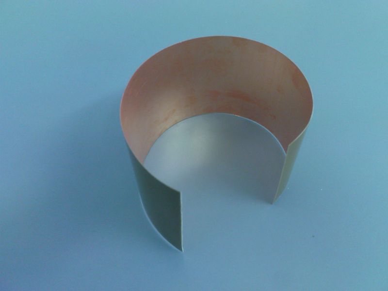
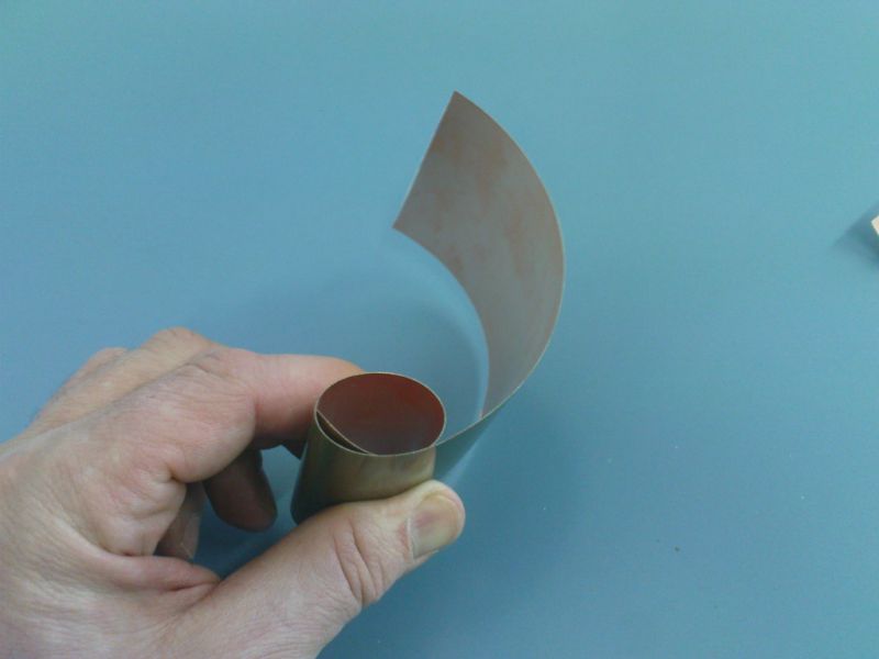
Background: We have also FR4 with a thickness of 0.125 mm carrier and 35μm copper layer (single or double sided) in stock. We sell this for the same price as 0.5 mm FR4 in size 510x1150mm. Cutting service is possible.
With these thin FR4 FR4 you have normal (solder) properties at an extremely small bending radius (see photo). Perhaps that would help you already?
By the way, I love the "Isolation Milling vs. Etching" statement on your web site, I couldn't agree more. Last year we bought a chemical processing line for PCB prototyping while other universities spend about the same amount of money on routers from your competitor near Hannover. Since then we made hundreds of industry-quality PCBs while they keep their ProtoMats on display, as rare artifacts. Once the process is established the costs of etching PCBs is a tiny fraction of the costs of isolation milling. The only problem was that we had to drill the holes manually, which hopefully will be solved now...
Best regards,
Marius RANGU, PhD
----------------------------------------------
"Politehnica" University of Timisoara, RO Electronics and Telecommunications Faculty 2
The Bungard CCD comes with a universal clamp fixture system where you can put your board or your ready-cut front panel in a predefined Zero position. Secondly you are free to prepare any drill base sheet with two or more fixing holes that you may use with reference pins. This way of mounting the boards is essential if you have to mount a board on the machine more than once or if you have to turn it over for double side milling.
Only with a motor driven Z axis you have control over the actual penetration depth and Z stroke speed, which are both indispensible parameters if you want more than stamping the holes in the board. We understood that LPKF machines cannot even drill / cut deeper than 2 mm, and in absence of a defined drill speed, we even heard about problems with PTH due to poor wall quality of the drill holes. With our motor driven Z axis you have an active stroke length of more than 30 mm, and the board penetration depth is limited only by the type of tool being used. And if we tell our software to cut 3.0 mm deep with 5 m/min stroke speed, (maybe in 3 iterations of 1.0 mm per turn) then it will cut exactly this depth at that speed, without fiddeling around on mechanical adjustment screws.
Really good layouts are essential, but can be archieved only.
1) with a laser plotter (like our movie stars, see website) However, this device will cost € 6950!
2) or from a layout or printer service Laser printers and bubble jets are always a compromise. Laser printer toner distribution is not correct, especially for large areas, because A4 sheets, toner drum need two turns, and the second half toner applicaton is weak. Remedy here, if you make two printouts, and both sets of each other, the toner density is almost perfect, because the toner error can not be reproduced. Bubble Jet (inkjet) are far better. When ink nozzle is clean and colour is full, layout is black! But, good combination of overhead foil and colour is important. For sure, your local office supplies dealer will help. As just a neutral market observer, and found, that we have had several positiv feedbacks and excellent results with bubble jets of Epson 1500 series, which end up in perfectly scaled and dark black layouts.
Yes, that is one of the applications that we designed it for. You can also mill / route aluminium or other material like plastics or even wood. And please ask our competitors if they have a motor driven Z axis that would allow a defined depth and stroke speed.

Rilkestrasse 1
D-51570 Windeck
+49 2292 / 9 28 28 - 29

 DE
DE  EN
EN  ES
ES  FR
FR 
